Logo


HomeProductsContactInstallContact

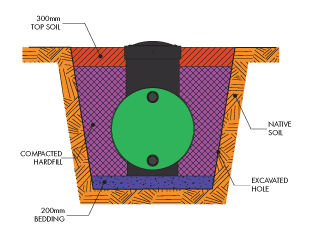
SUBS Installation Instructions


GENERAL
These installation instructions are applicable for Bailey Tanks underground stormwater tanks only and do not apply for any other tank type.
Failure to follow these guidelines may result in tank failure or tank flotation. It is important to read, understand and follow the instructions below. Contact Bailey Tanks with any variations.

The tank installation is the responsibility of the installer and Bailey Tanks do not provide any warranty for any installation.
The tank has been designed for light traffic loads only and shall not be placed under driveways and garages etc, where heavier loads are expected. The riser area shall not have traffic loads under any circumstances.

BEDDING AND BACKFILL MATERIAL
Bedding material shall consist of a minimum thickness of 200 mm compacted sand or pea gravel.
Backfill material shall consist of crushed stone or gravel, GAP20 or similar. All aggregates shall meet sections 4 and 5 or NZS 3121: 1986.
All excavated soil is to be removed from the area. Do not mix soil with backfill material.

EXCAVATION
Excavate a hole in the desired location to the depth as shown. Allow 200 mm bedding thickness at base of excavation. Allow minimum of 500 mm horizontal clearance between tank walls and excavated surfaces.
Allow for a safe working batter on walls of excavation. Under no circumstances shall workmen be allowed into an excavation without adequate safety equipment or without excavated walls at a safe batter. Consult OSH Guidelines

The excavation is required to be kept dry while backfilling proceeds. Pump any groundwater away from the area or provide adequate drainage.

BACKFILLING PROCEDURE
The following procedure should be followed:
Apply 200 mm bedding material and lightly compact to achieve a level surface.
Install Bailey tank to centre of hole.
Place backfill material in lifts of 300 mm. Each 300mm layer shall be lightly compacted using long handled stamper to remove air voids.
Backfill shall be pushed under the curved bottom portion of the tank in each 300mm lift. Use a compacter with a curved section to suit the curvature of the tank. Ensure the entire perimeter of the tank base is compacted.
Continue backfill to surface using compaction as required in 300 mm lifts. Topsoil may be used for the final 300mm layer.

NOTES
In an area where ground water levels are expected to be high or where ground permeability is low some form of restraint maybe required to prevent hydraulic uplift. It is the tank owner's responsibility to establish the ground water and soil conditions. If in doubt, refer to a Technical Representative or Geotechnical Engineer.
In certain soil conditions such as silt, peat or soft soils, filter fabric may be required between the native soil and the compacted hardfill.


Download Installation Instructions PDF

Install


Home
The new weapon in the war against stormwater dtention.

Solutions
Bailey Tanks Range of Underground Storm Water Retention/Detention Tanks

Contact
Bailey Tanks contact details North and South Islands


Architects
CAD Files
PDF Files

Installation
Engineered installation instructions

Bailey Tanks Limited

36 Ash Road, Wiri, Auckland, NZ
Telephone: +64 9 2627070
Facsmile: +64 9 2627071

52 Hickory Place, Hornby, Christchurch, NZ
Telephone: +64 3 3441260
Facsimile: +64 3 3441261

Email: info@tanks.co.nz

Copyright 2011 Bailey Tanks Limited New Zealand. All rights reserved